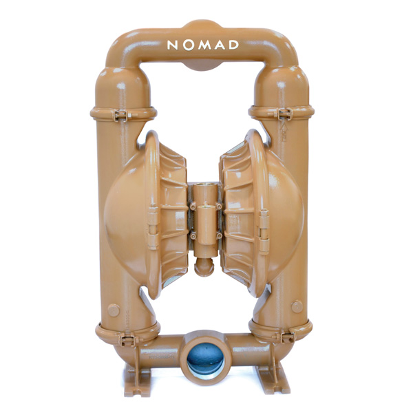
Nomad Air Pumps

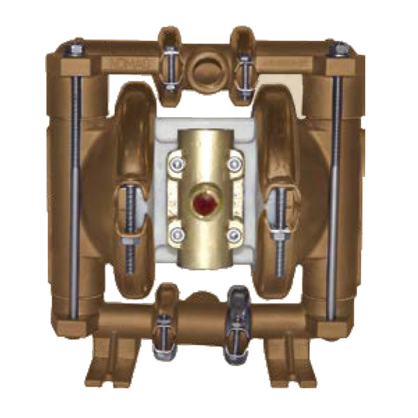
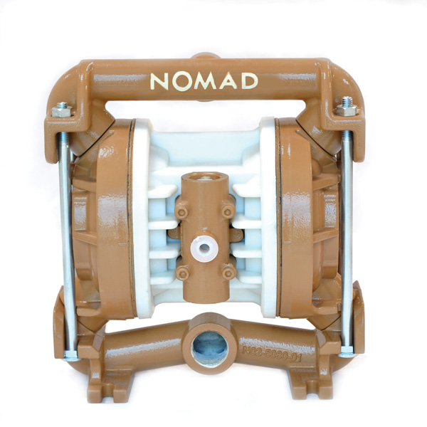
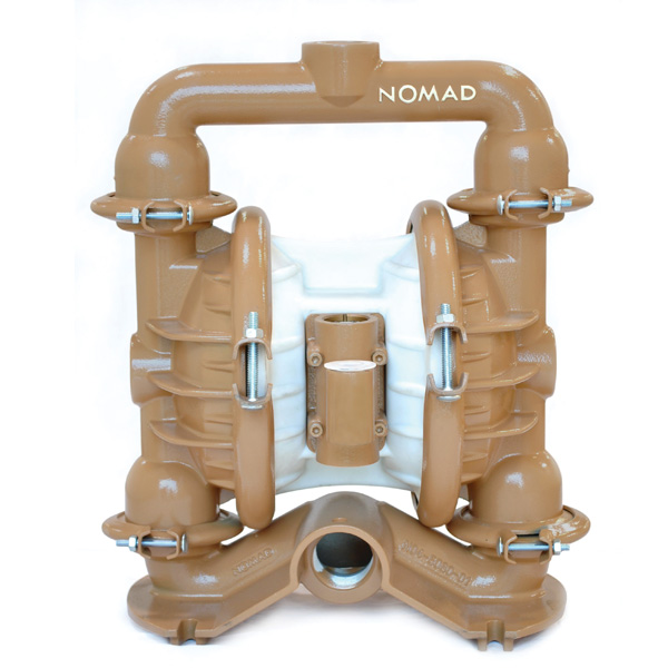
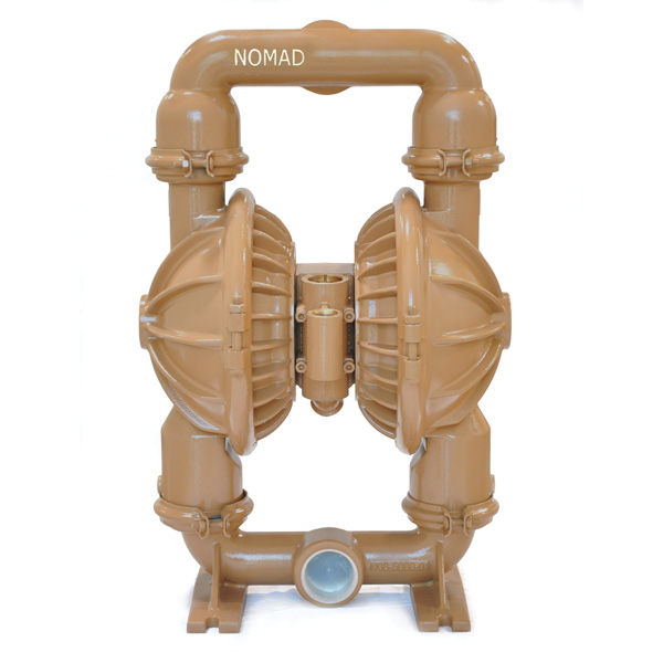
As the world’s largest and most experienced after-market pump product provider, NOMAD air pumps are highly versatile and offer great value for money against competing brands.
These lightweight, portable pumps are self-priming and can run dry indefinitely. They will stall when running against a shut valve. Flow is infinitely variable by adjusting the air supply. Pressures from 0-7 Bar are achievable.
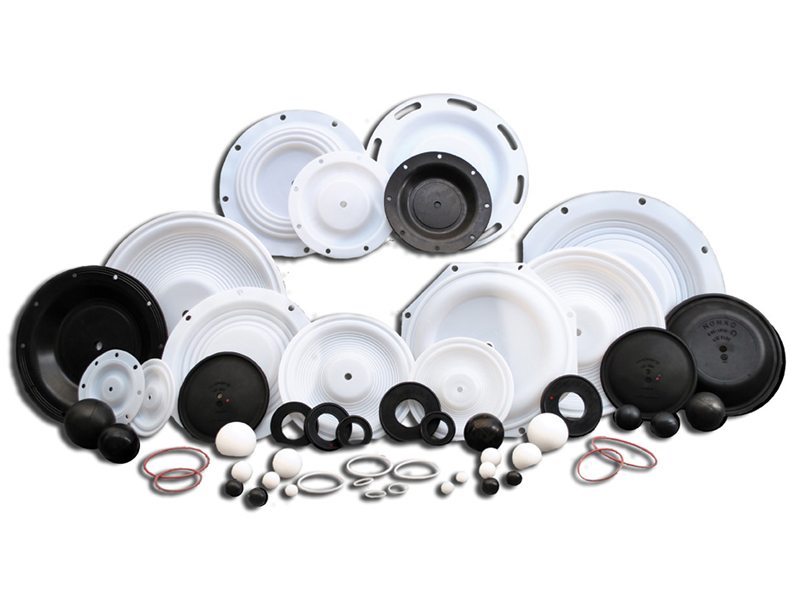
Pump construction is available in both Aluminium and Stainless steel with elastomers available in PTFE, Santoprene, Buna N / Nitrile and Neoprene dependent on application.
Download NOMAD Brochure
Pump Models
Air Operated Double Diaphragm Pumps Functionality and Flow Pattern

Figure 1
The air valve directs pressurized air to the back side of diaphragm A. Compressed air is applied directly to the liquid column separated by elastomeric diaphragms. The diaphragm acts as a separation membrane between the compressed air and liquid, balancing the load and removing mechanical stress from the diaphragm. The opposite diaphragm is pulled in by the shaft connected to the pressurized diaphragm. Diaphragm B is on its suction stroke; air behind the diaphragm has been forced out to the atmosphere through the exhaust port of the pump. Atmospheric pressure forces fluid into the inlet manifold forcing the inlet valve ball off its seat. The liquid is free to move past the inlet valve ball and fill the liquid chamber (see shaded area).

Figure 2
When the pressurized diaphragm, diaphragm A, reaches the limit of its discharge stroke, the air valve redirects pressurized air to the back side of diaphragm B. The pressurized air forces diaphragm B away from the center block while pulling diaphragm A to the center block. Diaphragm B is now on its discharge stroke. These same hydraulic forces lift the discharge valve ball off its seat, while the opposite discharge valve ball is forced onto its seat, forcing the fluid to flow through the pump discharge. Atmospheric pressure forces fluid into the inlet manifold of the pump. The inlet valve ball is forced off its seat allowing the fluid being pumped to fill the liquid chamber.

Figure 3
At the completion of the stroke, the air valve again redirects air to the back side of diaphragm A, which starts diaphragm B on its exhaust stroke. As the pump reaches its original starting point, each diaphragm has gone through one exhaust and one discharge stroke. This constitutes one complete pumping cycle. The pump may take several cycles to completely prime depending on the conditions of the application.
Temperature Limits for Elastomers
| Santoprene | -40.0°C to 107.2°C | -40.0°F to +225°F |
| Neoprene | -17.8°C to 93.3°C | -17.8°F to +200°F |
| Buna-N | -12.2°C to 82.2°C | -12.2°F to +180°F |
| Nordel | -51.1°C to 137.8°C | -51.1°F to +280°F |
| Viton | -40.0°C to 176.7°C | -40.0°F to +350°F |
| PTFE | -4.4°C to 104.4°C | -40°F to 220°F |
NOTE:
These are average temperatures. Chemicals and solvents can have an effect on temperature limits.
Please feel free to get in contact should you have any queries regarding how we can help make the breakdowns and maintenance of your pumps as hassle-free as possible.
Contact us
