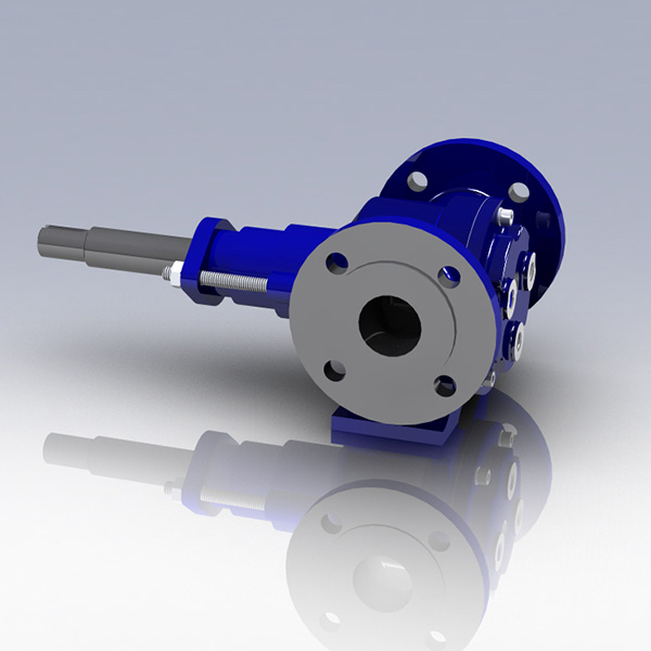
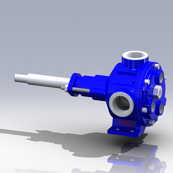
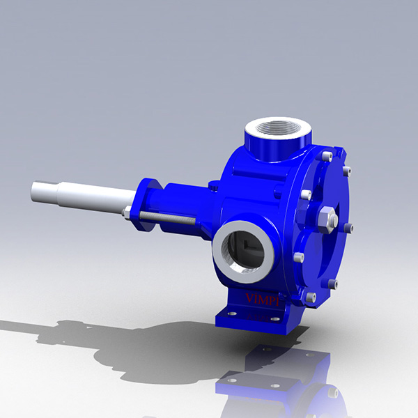
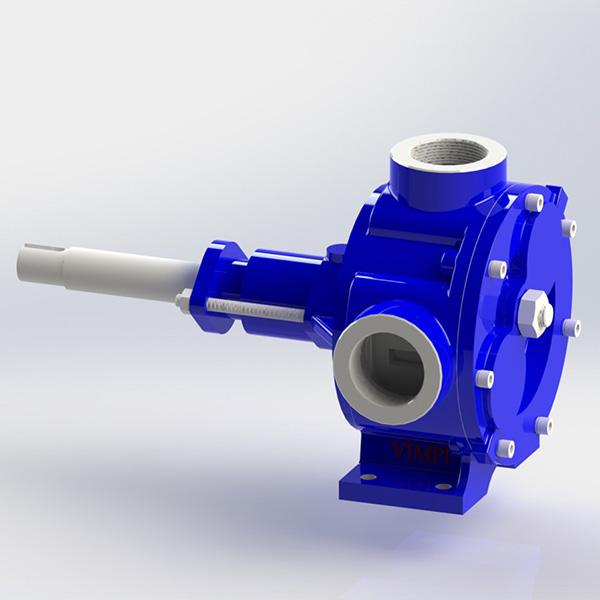
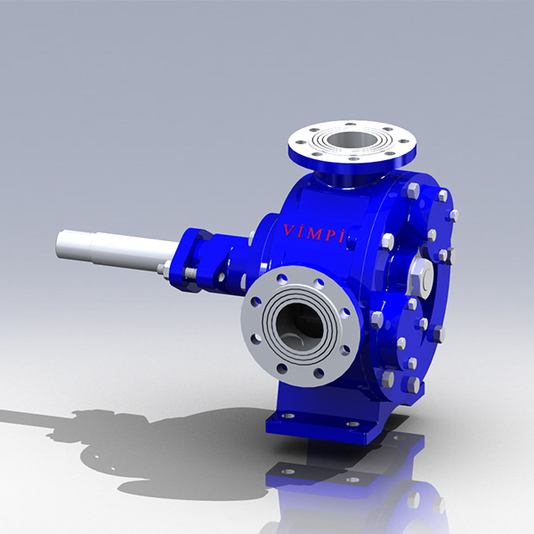
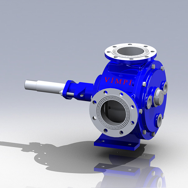
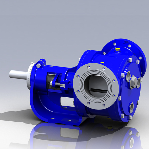
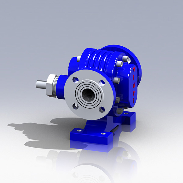
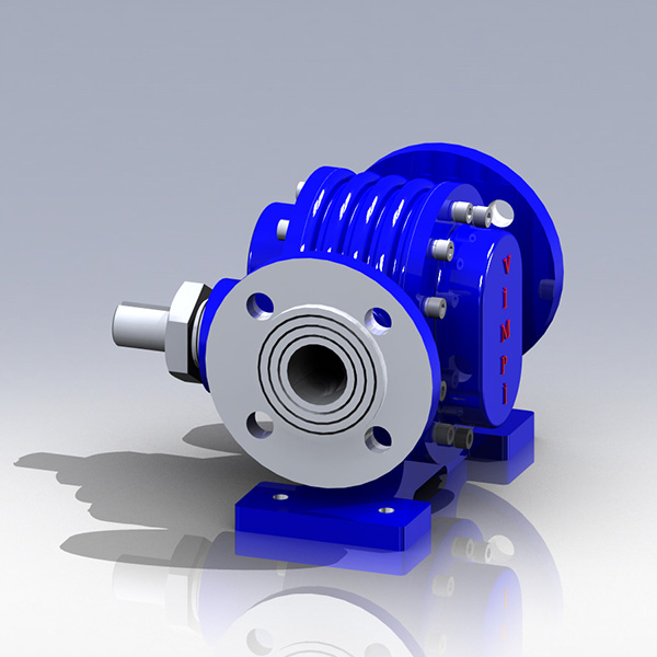
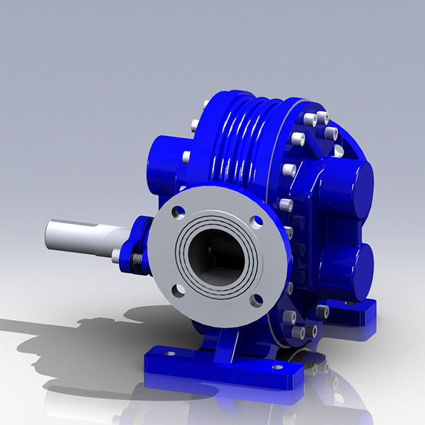
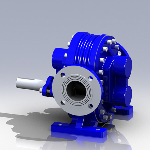
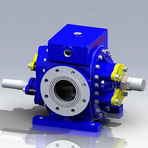
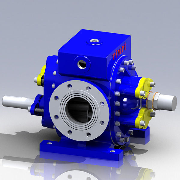
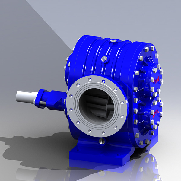
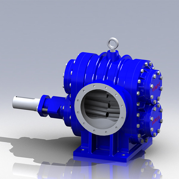
Vimpi Gear Pumps

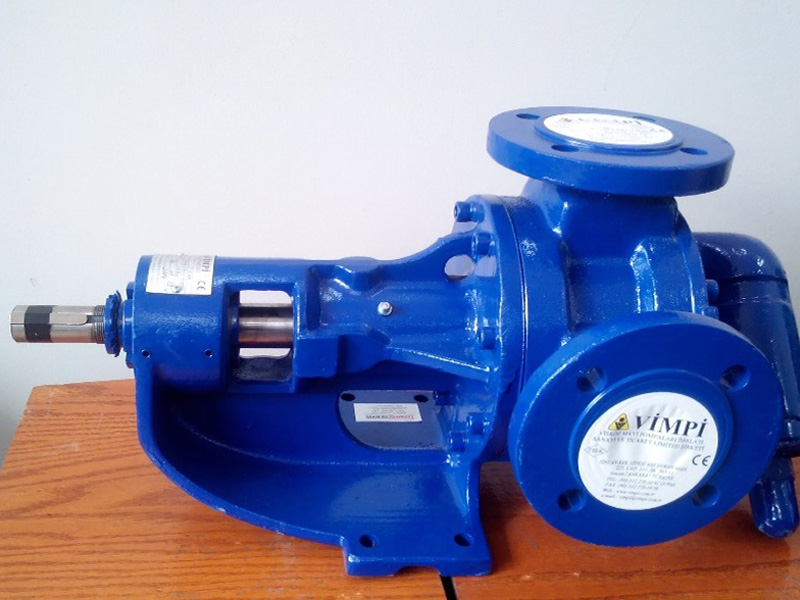
Pump Solutions have been agents for Vimpi, supplying gear pumps, hot oil centrifugal pumps, valves and other ancillary equipment since 1999.
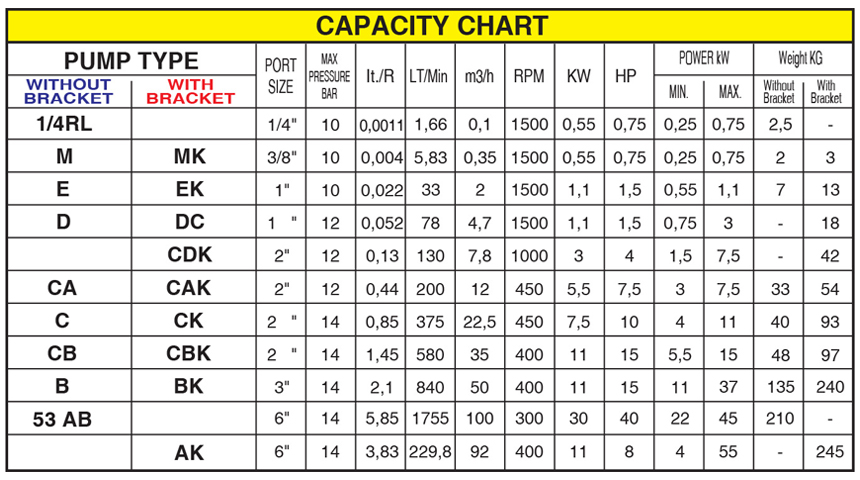
The pumps are able to handle both very thin and viscous liquids up to 2,000,000 SSU. They can also achieve capacities of up to 120m³/h and temperatures up to 400°C.
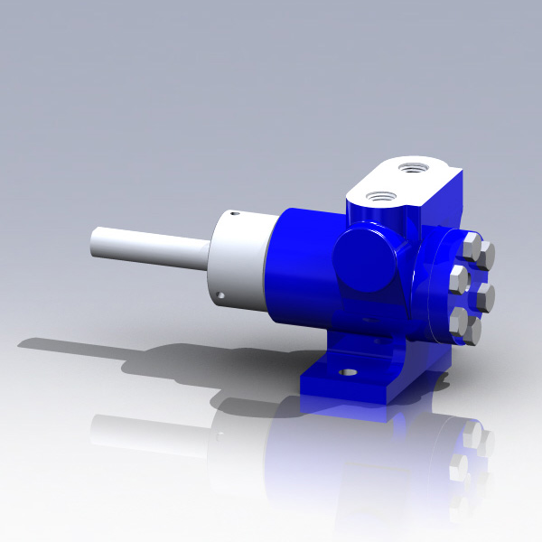
The pumps are available in general-purpose bareshaft or heavy-duty bracketed (K model) configurations and can be supplied with internal relief valves to prevent damage to the pump or system.
Materials of construction include cast iron, bronze, steel and stainless steel. Bushes are also available in carbon graphite and tungsten carbon, dependent on application.
Download Vimpi Brochure
Download Vimpi User Manual
Pump Models
Internal Gear Pumps
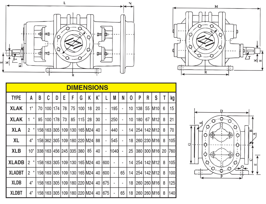
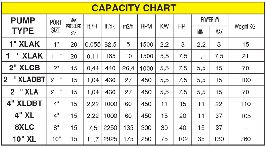
External gear pumps
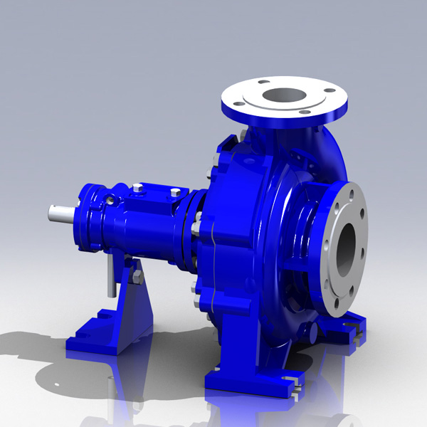
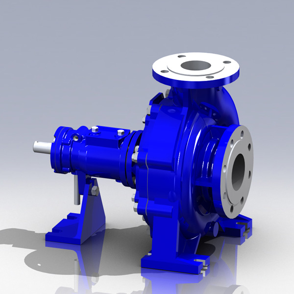
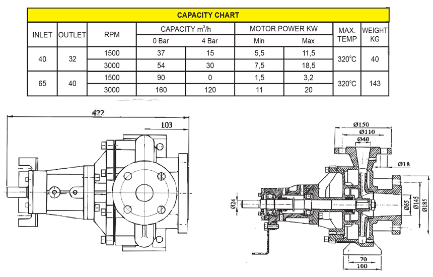
Centrifugal pumps
P3 Vane Pump
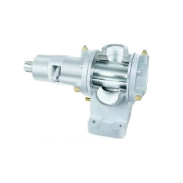
Internal gear pumps
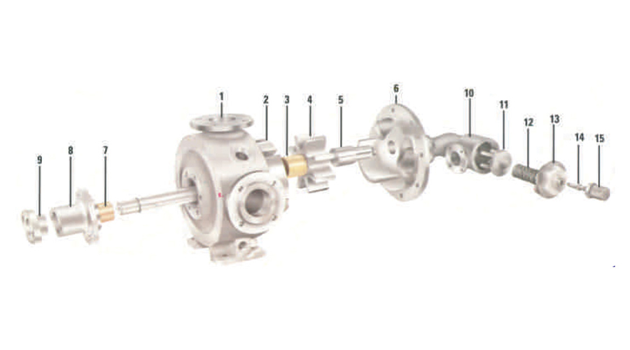
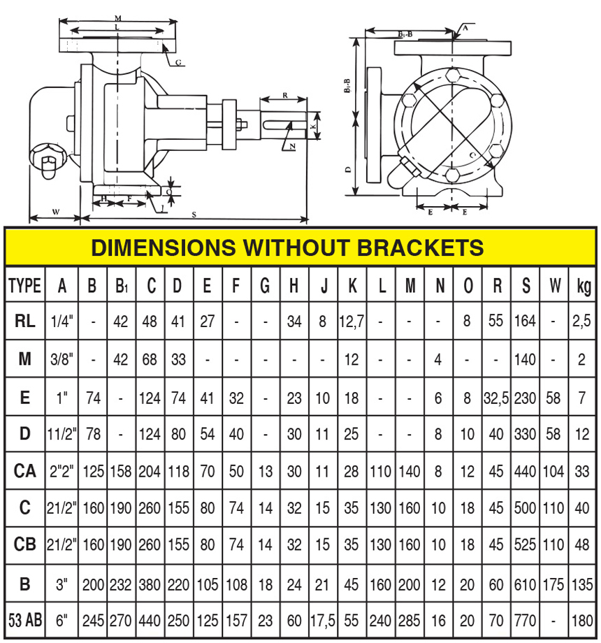
Internal Pump Without Bracket
- Casing
- Rotor and Shaft
- Idler Bush
- Idler
- Idler Pin
- Head
- Main Bushing
- Stuffing Box
- Gland
- B-Pass Bod
- Clack
- Spring
- B-Pass Cover
- Adjusting Bolt
- Cap
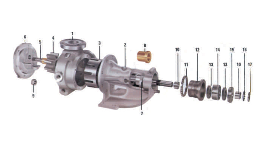
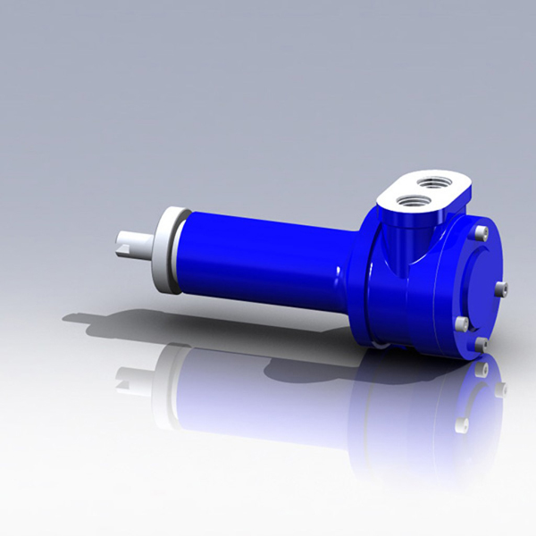
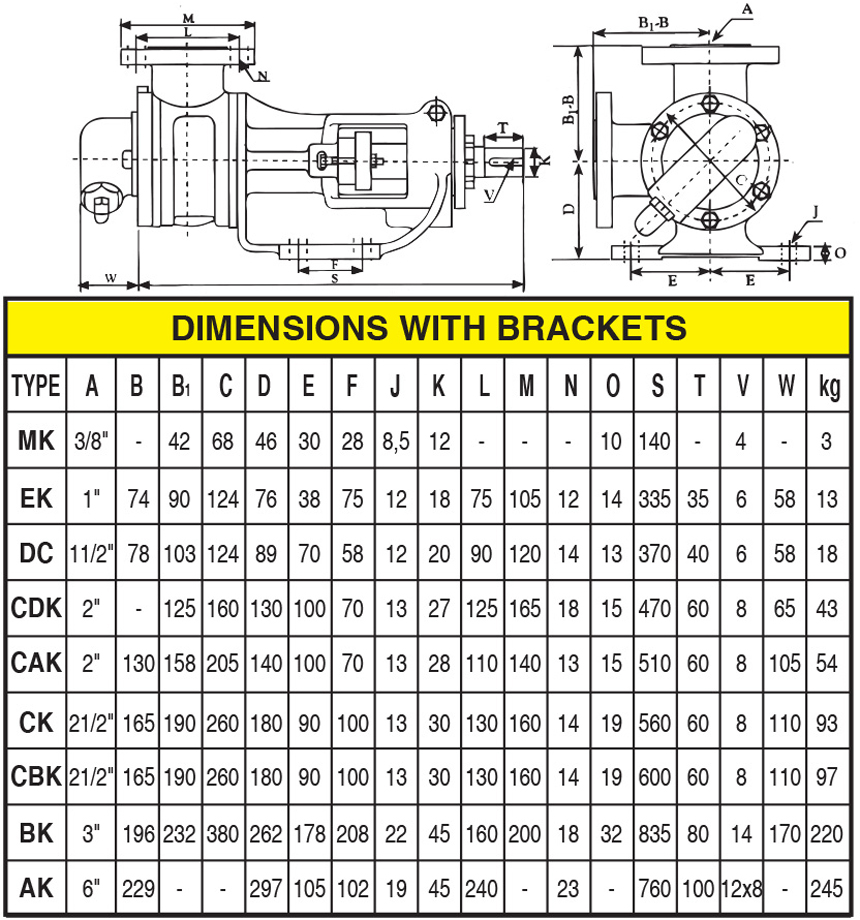
Internal Pump With Bracket
- Casing
- Bracket
- Rotor and Shaft
- Idler
- Idler Pin
- Head
- Gland
- Main Bushing
- Nut
- Sleeve
- Ring
- Adjust Drum
- Lip Seal
- Roller Bearing
- Nut
- Locking Sheet
- Nut
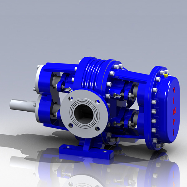
External gear pumps
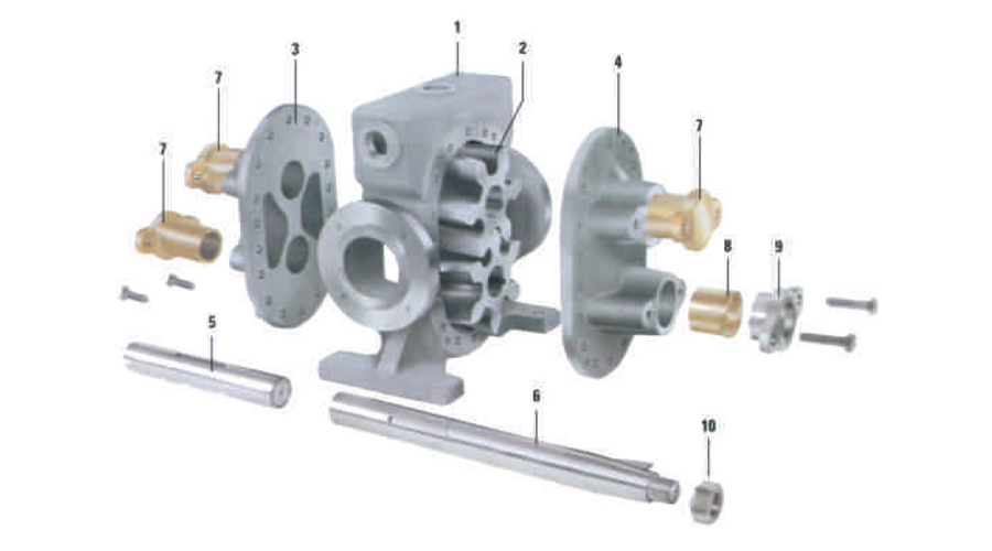
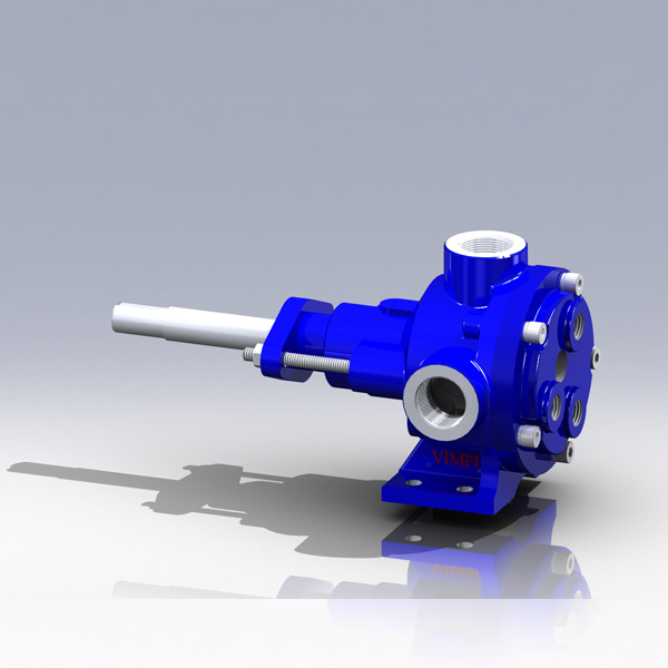
External Pump
- Casing
- Rotor and Shaft
- Idler Bush
- Idler
- Idler Pin
- Head
- Main Bushing
- Stuffing Box
- Gland
- B-Pass Bod
- Clack
- Spring
- B-Pass Cover
- Adjusting Bolt
- Cap
Centrifugal pumps
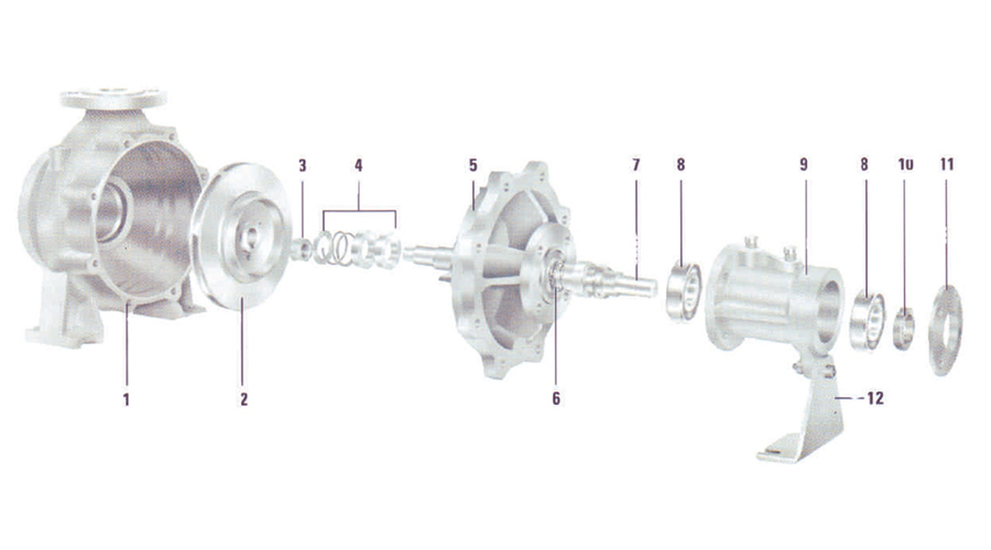
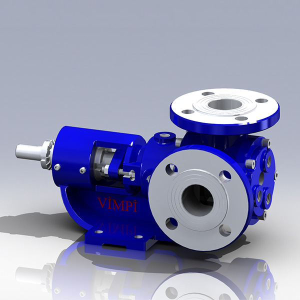
Centrifugal Pump
- Main Body
- Impeller
- Impeller Nut
- Packing
- Front Cover
- Mechanical Seal
- Pump Shaft
- Ball Bearing
- Port
- Lip Seal
- Ball Bearing Cover
- Foot
P3 Vane pump
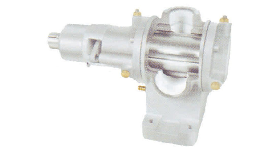
Vane Pump
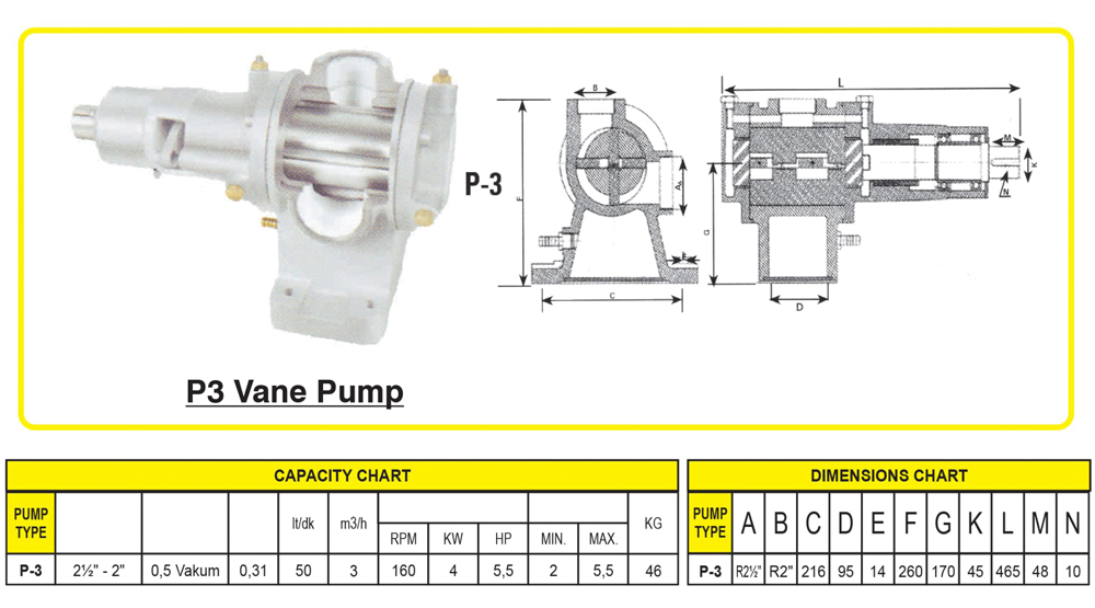

Internal Operation

Operating Principle:
Internally the pump has two gears and a crescent. The rotor (large gear) is driven by the motor and drives the idler gear. As the gears unmesh, liquid is drawn into the pump (1). The crescent separates the liquid and acts as a seal between the rotor and the idler (2). In (3) the pump casing is full of liquid. As the gears mesh (4) the liquid is forced out of the discharge port. This action gives continuous non-pulsating flow.
External Operation

Operating Principle:
The external pump also has a drive gear (driven by the powers source) and a driven gear. The gears run in opposite directions (1) and the liquid carried around the outside between the gears and the casting (2). As the gears re-mesh on the discharge side, the liquid is forced out into the discharge line. The action gives a continuous non-pulsating flow.
Please feel free to get in contact should you have any queries regarding how we can help make the breakdowns and maintenance of your pumps as hassle-free as possible.
Contact us
